Difference between revisions of "Workshop: Introduction to Microcontrollers with Arduino"
(add download links) |
(begin major fixes) |
||
| Line 8: | Line 8: | ||
You’re also going to be using a different microcontroller for this lab. Instead of the Xplained, you’ll be using a device called the Teensy 3.2. As its name suggests, it’s pretty small! As such, the silkscreen (the text that appears on the faces of the printed circuit board, usually indicating things like pin labels) is minimal. In order to actually utilize the Teensy, you’ll need its pinout. | You’re also going to be using a different microcontroller for this lab. Instead of the Xplained, you’ll be using a device called the Teensy 3.2. As its name suggests, it’s pretty small! As such, the silkscreen (the text that appears on the faces of the printed circuit board, usually indicating things like pin labels) is minimal. In order to actually utilize the Teensy, you’ll need its pinout. | ||
| − | |||
| − | |||
| − | |||
'''This workshop will consist of two main objectives; how to control Digital output and inputs and how to control an analog output and input''' | '''This workshop will consist of two main objectives; how to control Digital output and inputs and how to control an analog output and input''' | ||
| Line 18: | Line 15: | ||
(basic outline) | (basic outline) | ||
| + | == Software setup == | ||
| + | |||
| + | You're going to need two pieces of software to work with the microcontroller. | ||
| + | |||
| + | === Download and install === | ||
# Download and install the [https://www.arduino.cc/en/main/software Arduino IDE] on your operating system of choice. ''(Note: if you're using Windows, use the installer, not the app!)'' | # Download and install the [https://www.arduino.cc/en/main/software Arduino IDE] on your operating system of choice. ''(Note: if you're using Windows, use the installer, not the app!)'' | ||
| − | |||
# Download and install [https://www.pjrc.com/teensy/td_download.html Teensyduino], which adds Teensy support to the Arduino IDE. Just follow the prompts; you don’t need to install all the libraries, but if you ever want to work with Teensies in the future, it’s worth taking the time to install them now. | # Download and install [https://www.pjrc.com/teensy/td_download.html Teensyduino], which adds Teensy support to the Arduino IDE. Just follow the prompts; you don’t need to install all the libraries, but if you ever want to work with Teensies in the future, it’s worth taking the time to install them now. | ||
| + | === The which, the where, and the how === | ||
| + | In order to get the Arduino IDE up and running with your board - regardless of which board it happens to be - you must answer for it three questions: the which, the where, and the how. | ||
| − | + | # Which board are you using?\ | |
| − | Windows: select COMX, where X is the largest number (it should also say Teensy 3.2) | + | #* Navigate to ''Tools → Board'' and select ''Teensy 3.2 / 3.1'' |
| − | OSX: select /dev/cu.usbmodemXXXXXX, where XXXXXX is some number. This may not show up with Teensy. | + | # Where is the board connected? |
| − | (You can see that neither of these operating systems handle hardware communication ports very elegantly.) | + | #* Navigate to ''Tools → Port'' and: |
| − | + | #** Windows: select ''COMX'', where ''X'' is the largest number (it should also say Teensy 3.2) | |
| − | the default programmer | + | #** OSX: select ''/dev/cu.usbmodemXXXXXX'', where ''XXXXXX'' is some number. This may not show up with Teensy. |
| − | + | #** (You can see that neither of these operating systems handle hardware communication ports very elegantly.) | |
| − | + | # How are you programming the board? So far, you’ve used the mEDBG device for programming. Teensy won’t work with that - but it will work with the default programmer, the AVRISP mkII. | |
| − | + | #* Navigate to ''Tools → Programmer'' and select ''AVRISP mkII''. | |
| − | |||
| − | |||
| − | |||
| − | |||
| − | |||
| − | |||
| − | |||
| − | |||
| − | + | == Activity 01: Digital output (aka 'Hello World' for hardware) == | |
| + | This activity sees you using a pin on the microcontroller to blink an LED. | ||
| − | + | # Navigate to ''File → Examples → 01.Basics → Blink''.<br>The code which appears should look something like this:<br>[[File:code for teensy.png]] | |
| + | # Upload the code to your board using the button or CTRL+U. This is actually a compile and program. If you get any errors, ask for help. Assuming it has programmed correctly, you should now see the onboard LED blinking! | ||
| + | # Fiddle with the delay times and reprogram to see how you can affect the speed of the LED blinking. | ||
| + | # Connect an LED and a 220Ω resistor (just like in previous labs) to D9, and then change to code to reference this new LED’s pin. | ||
| + | # Compile and Program to test. | ||
| + | '''NOTE: There is a button on the Teensy. This button does not do what you think it does. This button is a program button, meaning that when you press it, the device takes the most-recently compiled code and sticks it in its program memory. This is not a reset button!''' | ||
| − | == Digital Input== | + | == Activity 02: Digital Input (aka a button) == |
1.Navigate to File → Examples → 02.Digital → Button. | 1.Navigate to File → Examples → 02.Digital → Button. | ||
Revision as of 13:49, 20 February 2019
Contents
Intro
You are going to be programming with Arduino. Arduino can refer to many things (a company, a software suite, a board, a programming language); in general, Arduino is an ecosystem in which you can conveniently program microcontrollers to interact with the outside world. It’s the easiest (as well as most ubiquitous) way to connect hardware with software, and the easiest way to get into embedded programming.
The Arduino IDE is a software suite which packages up all the functionality of programming microcontrollers in a higher level language (in this case, the Arduino language!). Its underlying compiler inherits from the C++ language (and by extension, C), so to those who have used C++, C, or any language with a C-like syntax, this will look very familiar.
You’re also going to be using a different microcontroller for this lab. Instead of the Xplained, you’ll be using a device called the Teensy 3.2. As its name suggests, it’s pretty small! As such, the silkscreen (the text that appears on the faces of the printed circuit board, usually indicating things like pin labels) is minimal. In order to actually utilize the Teensy, you’ll need its pinout.
This workshop will consist of two main objectives; how to control Digital output and inputs and how to control an analog output and input
(basic outline)
Software setup
You're going to need two pieces of software to work with the microcontroller.
Download and install
- Download and install the Arduino IDE on your operating system of choice. (Note: if you're using Windows, use the installer, not the app!)
- Download and install Teensyduino, which adds Teensy support to the Arduino IDE. Just follow the prompts; you don’t need to install all the libraries, but if you ever want to work with Teensies in the future, it’s worth taking the time to install them now.
The which, the where, and the how
In order to get the Arduino IDE up and running with your board - regardless of which board it happens to be - you must answer for it three questions: the which, the where, and the how.
- Which board are you using?\
- Navigate to Tools → Board and select Teensy 3.2 / 3.1
- Where is the board connected?
- Navigate to Tools → Port and:
- Windows: select COMX, where X is the largest number (it should also say Teensy 3.2)
- OSX: select /dev/cu.usbmodemXXXXXX, where XXXXXX is some number. This may not show up with Teensy.
- (You can see that neither of these operating systems handle hardware communication ports very elegantly.)
- Navigate to Tools → Port and:
- How are you programming the board? So far, you’ve used the mEDBG device for programming. Teensy won’t work with that - but it will work with the default programmer, the AVRISP mkII.
- Navigate to Tools → Programmer and select AVRISP mkII.
Activity 01: Digital output (aka 'Hello World' for hardware)
This activity sees you using a pin on the microcontroller to blink an LED.
- Navigate to File → Examples → 01.Basics → Blink.
The code which appears should look something like this: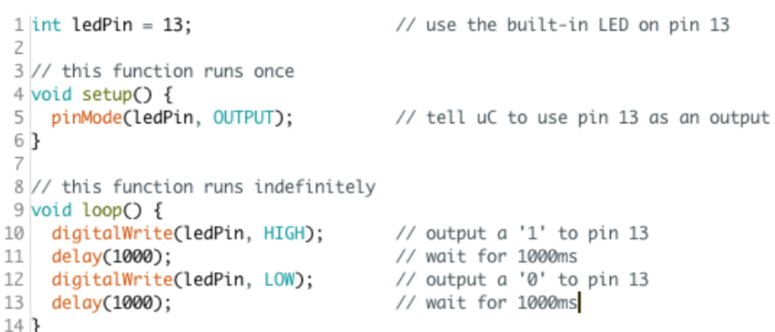
- Upload the code to your board using the button or CTRL+U. This is actually a compile and program. If you get any errors, ask for help. Assuming it has programmed correctly, you should now see the onboard LED blinking!
- Fiddle with the delay times and reprogram to see how you can affect the speed of the LED blinking.
- Connect an LED and a 220Ω resistor (just like in previous labs) to D9, and then change to code to reference this new LED’s pin.
- Compile and Program to test.

NOTE: There is a button on the Teensy. This button does not do what you think it does. This button is a program button, meaning that when you press it, the device takes the most-recently compiled code and sticks it in its program memory. This is not a reset button!
Activity 02: Digital Input (aka a button)
1.Navigate to File → Examples → 02.Digital → Button.
2.Connect a button to D8.
3.In the code, change the button pin to D8, and the LED pin to D9.
3a.pinMode(buttonPin, INPUT_PULLUP)
4.Compile and upload your code
5.Modify the code so that when you press the button he LED turns on, and when you are not pressing the button, the LED turns off.
Analog input
1.Navigate to File → Examples → 03.Analog → AnalogInput.
2.Change the LED pin to D9. Additionally, change the analog input pin to A5.
3.Compile and Program, and turn the pot to change the speed at which the LED blinks!
4.debug as necessary
5. In the setup function, add the following line:Serial.begin(9600)
6.This initializes the Serial communications protocol. Now, in loop, after you’ve read the value of the analog pin, add the following line: Serial.println(sensorValue);
7.Compile and program the code, and once it’s successful, open the Serial Monitor with or CTRL+SHIFT+M. You should see values printing out on this screen; turn the potentiometer, and the value will change! This number is what is being used as the delay time (in ms) in the code.
Analog output
1.Navigate to File → Examples → 03.Analog → Fading.
2.Compile and program the code. your LED’s brightness should be fading up and down.
Analog final
1.Create a project - call it Fade Control - that controls the brightness of an LED. It has two modes: Automatic and Manual. In Automatic mode, it will fade the brightness of the LED up and down (just like Activity 04). In Manual mode, the position of the potentiometer determines the brightness of the LED. The mode can be switched by pressing a button